
Application of the VDM-based methodology to civil engineering
The VDM-based method of damage identification combined with strain measurements using piezoelectric patch sensors has been applied to structural health monitoring of a railway truss bridge [25]. The investigated object is a typical railway truss bridge spanning a channel in Nieporet near Warsaw. There are several hundreds of similar bridges of various spans all over Poland. The bridge, shown in Fig. 1, is made of steel and has a span of 40 m and height of 8 m. There is just one rail track on the bridge so it is not prone to torsion when loaded by a train. Like many other bridges it is just visually inspected once in a few years for maintenance.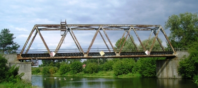
Fig. 1 Investigated railway truss bridge in Nieporet
The idea of weigh in motion (WIM) was reported many years ago. In the described system it provides a load input for modelling of bridge responses. The idea is somewhat similar to the ambient excitation in the sense of using an existing source, but is different in the sense of measuring the input force. The WIM part is supposed to weigh the passing trains at their actual velocities. It should be mounted in the vicinity of a monitored bridge e.g. 50 m away. This part may also exist on its own to provide information about rail traffic.
The bridge monitoring part assumes a calibrated numerical model regularly supplied with measurement data sent remotely via the Global System for Mobile (GSM) communications. The data include both the load information from the WIM part and the bridge responses to passing trains. By determination of deviations in the measured bridge responses, exceeding a pre-defined threshold value, the damage detection stage is satisfactorily completed. The more advanced stage of damage identification employs a VDM-based numerical analysis, which points out defective elements of the monitored truss structure and quantifies the intensity of damage in such elements. With a record of archived results e.g. 3 year regular monitoring, the structural degradation rate might be assessed and a prognosis of remaining lifetime worked out.
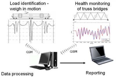
Fig. 2 The integrated monitoring system for railway truss bridges:
left - weigh in motion part, right - structural health monitoring part
References
- [25] Kolakowski P., Sala D., Sekula K., Swiercz A. (2009) A way of monitoring the truss structure of a bridge and a system of monitoring the truss structure of a bridge, patent pending application no. P 387115, Polish Patent Office (in Polish)
- [26] Kolakowski P., Sekula K., Sala D., Swiercz A., Orlowska A. (2009) Two-year monitoring campaign of a railway truss bridge, Proc. of the 3rd International Conference on Experimental Vibration Analysis for Civil Engineering Structures - EVACES09, Wroclaw, 14-16 October